Steps of Data Modeling
| Steps | Main output |
|---|---|
| 1. Requirement analysis (요구사항 분석) | Requirements Definition Document (요구사항 정의서) |
| 2. Conceptual Modeling (개념적 모델링) | ERD |
| 3. Logical Modeling (논리적 모델링) | Logical Data Model (논리 데이터 모델 (Table, 속성, 제약조건)) |
| 4. Physical Modeling (물리적 모델링) | Physical Data Model and DDL |
Tips
- Each design stage flows sequentially, but you must always consider the possibility of iteration (returning to a previous stage).
- If you don’t grasp the requirements accurately at the beginning, the cost of changing the database structure later becomes very high
- All tables must be documented with an ERD and a schema definition document to make future maintenance easier.
1. Requirement Analysis
Goals
- Figure out what data the system needs to handle
- Extract the main entities, actions, and rules
- final output - Requirements Definition Document
- 요구사항 분석 - 코드잇 노트
Practical Example
- Information needed for user registration: name, email, phone number, password.
- A user can write a post (identify the relationship).
Key Deliverables
| Deliverable Item | Description |
|---|---|
| Entity List | Identifies what entities exist (e.g., Member, Post, Comment). |
| Attribute List | Lists the main information each entity has (e.g., Member → name, email). |
| Relationship Derivation | Defines the connectivity between entities (1:1, 1:N, N:M). |
- Requirements Definition Document (요구사항 정의서)
- Contains the key deliverables
- The final output for this stage
- Examples
2. Conceptual Modeling
Goals
- Visually represent the entire data structure from a user’s perspective.
- Define entities, attributes, and relationships using an ERD (Entity-Relationship Diagram).
- final output: ERD
- 개념적 모델링 - 코드잇 노트
- diagram

- ERD (Entity Relationship Diagram) ⇒ used for visualization!
Entities
- Creating entities - 엔티티 도출
- ⭐ Defining entity relationships - 엔티티 간 관계 정의
- Cardinality
- junction table or join table
- for many-to-many (N:M) relationships → the relationship can only be implemented like this
Important notes
| Concept | Description | Example |
|---|---|---|
| 1:1 Relationship | One entity is connected to only one other entity. | User ↔ National ID Card |
| 1:N Relationship | One is connected to many, but the reverse is a connection to only one. | User → Post |
| N:M Relationship | Many are connected to many → A junction table is needed. | Student ↔ Course |
| Mandatory/Optional Relationship | Distinguishes whether the existence of the relationship is required or optional. | A user can optionally have a profile image. |
| Physical Implementation Considerations | Includes FK constraints, ON DELETE actions, junction tables, index configuration, etc. | Maintaining referential integrity and optimizing performance. |
Key Deliverables
| Item | Description |
|---|---|
| ERD | Visually represents the relationships between entities. |
| Definition Document | Includes descriptions for each entity, attribute, and relationship. |
ERD (Entity-Relationship Diagram)
Definition
An ERD is a diagram that visually represents real-world objects (entities) and the relationships between them. (see diagram)
- It is a fundamental tool used to logically design a data structure.
- The final output for this stage
- https://calm-individual-12a.notion.site/ERD-230c6b709828818ebccbdb0974b10aa0
- Example:
dbdiagram.io,ERDCloud,Draw.io- diagram (
ERDCloud)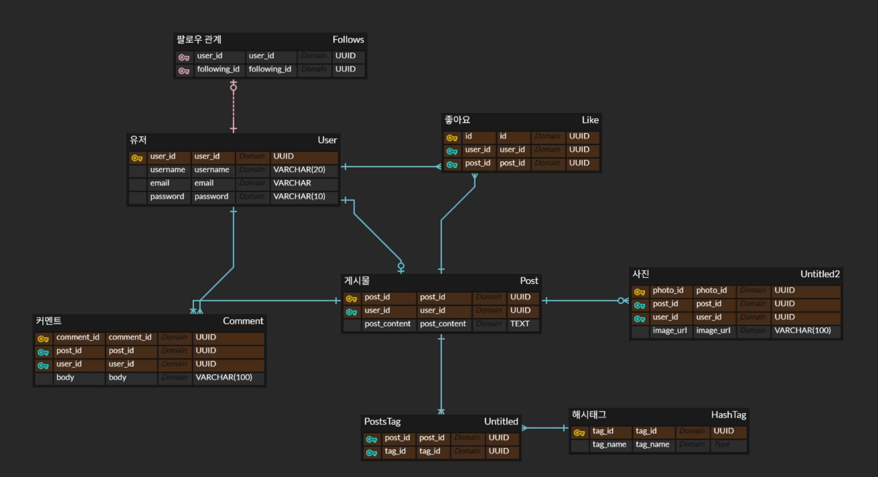
- diagram (
- Components
- Entity -The main unit where data is stored (e.g.,
Member,Product). - Attribute -The detailed information of an entity (e.g.,
name,age,price). - Relationship - The relationship between entities (e.g., “A member creates an order”).
- Entity -The main unit where data is stored (e.g.,
3. Logical Modeling
Goal
The process of expressing the relationships between entities and attributes, which have been identified based on user requirements, into a formalized structure
- An abstraction step that utilizes ERD (Entity-Relationship Diagram) tools to visually design the model
- Goals
- To derive a normalized relational structure that is independent of any specific DBMS.
- To clearly establish Primary Keys (PK), Foreign Keys (FK), and other constraints.
- final output: Logical Data Model
- 논리적 모델링 - 코드잇 노트
- Can be used before the project starts or if the db is not decided yet
- Uses ERD tools to define the following elements:
- Entity
- Represented by a rectangle.
- Attribute
- A specific data item that an entity possesses. For example, a “
Member” entity has attributes like “name,” “email,” and “phoneNumber.” - Represented as ovals or listed inside the entity rectangle (like fields in a class).
- A specific data item that an entity possesses. For example, a “
- Relationship
- Represented by a line connecting the entities on the diagram.
- Entity
Keys / identifiers
Logical Modeling - the process/design phase
- Translates the high-level ERD into a detailed structure.
- Applies normalization rules to reduce redundancy.
- Defines tables, columns, and relationships in a way that is independent of any specific database software (like PostgreSQL or MySQL).
Logical Data Model/Schema Definition Document (The Blueprint 📄)
This is the final document that you produce as the result of the logical modeling process. It’s the tangible blueprint that contains all the details, including:
- Table Names
- Column Names and their data types
- Constraints (
PRIMARY KEY,FOREIGN KEY,NOT NULL, etc.)
Example
simple example of what a Logical Data Model looks like

-- 논리 모델을 반영한 테이블 정의 예시
CREATE TABLE members (
    member_id SERIAL PRIMARY KEY,
    name VARCHAR(50) NOT NULL,
    email VARCHAR(50) UNIQUE NOT NULL
);

CREATE TABLE orders (
    id SERIAL PRIMARY KEY,
    member_id INTEGER NOT NULL REFERENCES members(id),
    order_date TIMESTAMP DEFAULT now()
);
--
Table: Member
- id: PRIMARY KEY, 자동증가
- name: 최대50개 문자열, NULL 허용 안함
- email: 최대100개 문자열, NULL 허용 안함, 고유한 값

Table: Order
- id: PRIMARY KEY, 자동증가
- member_id: Member를 참조하는 외래키(member_id)
- order_date: 날짜 데이터, 생성시점에 초기값 지정
4. Physical Modeling
Goals
- The logical modeling is independent of DBMS, but physical modeling is dependent
- 특정 db에 맞춰서 실제 스키마 구현
- 성능적인 것들은 db마다 하는 법이 다름..그래서 이 단계에서 구현함
- steps
- Creating tables
- Dealing with keys
- Referential integrity -
CASCADE,SET NULL,RESTRICT - Indexing - critical for performance
Example
The physical design phase includes creating indexes and optimizing database-specific features.
-- Considering an index in the physical design
CREATE INDEX idx_posts_member_id ON posts(member_id);

-- Optimizing an auto-generated sequence
ALTER SEQUENCE members_member_id_seq CACHE 50;
Key Considerations
| Element | Description |
|---|---|
| Index | Apply to columns that are frequently queried or used in JOINs. |
| Partitioning | Divide very large tables into smaller chunks based on a specific range or rule. |
| Tablespace | Consider distributing data across different physical storage devices. |
Physical Data Model and DDL
- The Physical Data Model transforms the logical model into a structure that can be deployed on an actual DBMS.
- The final output for this phase
- It uses DDL (SQL) to create the tables, indexes, and constraints.
Example SQL
CREATE TABLE member (
  id SERIAL PRIMARY KEY,
  name VARCHAR(50) NOT NULL,
  email VARCHAR(100) NOT NULL UNIQUE
);

CREATE TABLE orders (
  id SERIAL PRIMARY KEY,
  member_id INTEGER NOT NULL REFERENCES member(id),
  order_date TIMESTAMP DEFAULT now()
);